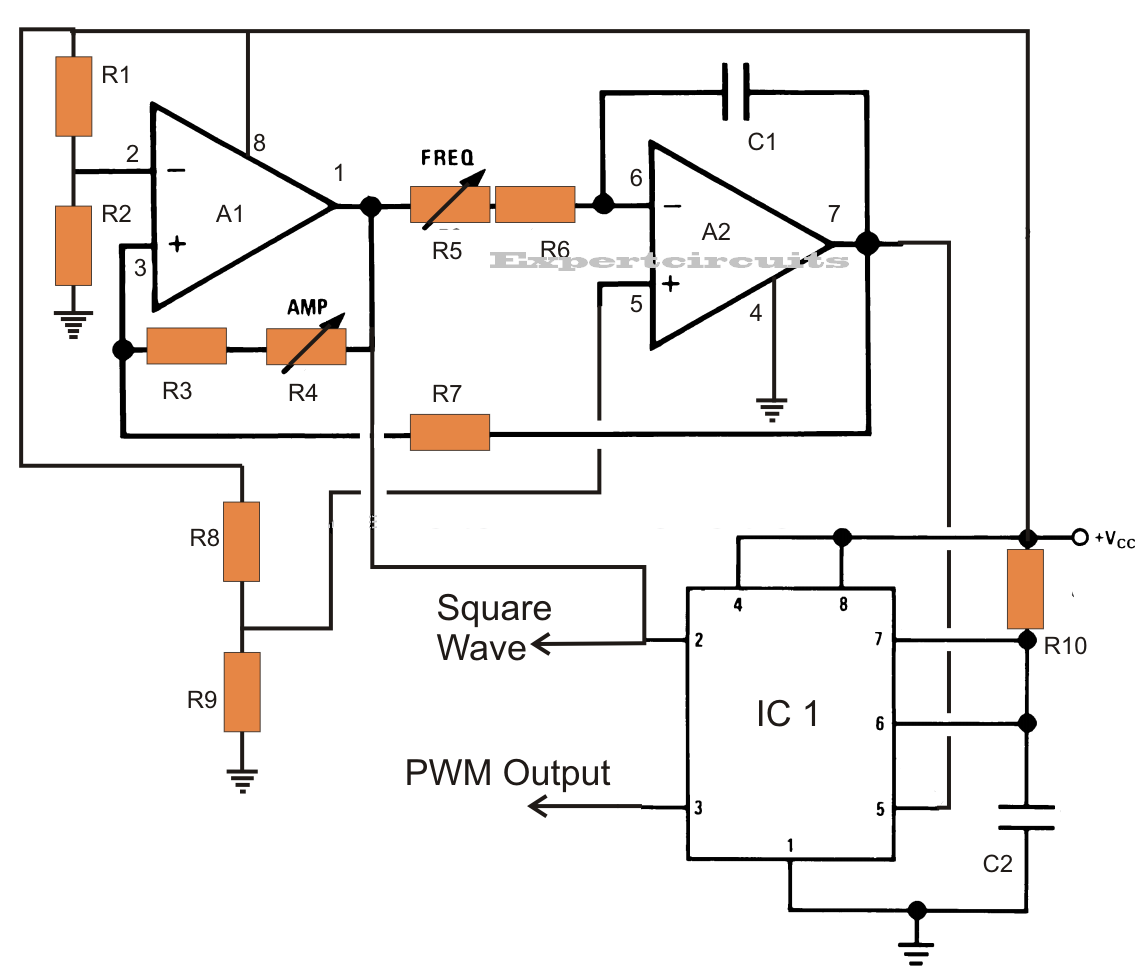
They are also called power inverters. 100 watt inverter circuit diagram parts list design tips. Originally i used a 555 timer and a cd4017 decade counter to produce the modified sine wave but then i thought a simple pic micro controller with its internal clock would produce a stable 50hz60hz frequency without the need.
pure sine wave inverter circuit diagram

Here a simple voltage driven inverter circuit using power transistors as switching devices is build which converts 12v dc signal to single phase 220v ac.
Pure sine wave inverter circuit diagram. Thanks for sharing a good schematic of pure sine wave inverter i want to build this inverter and require following information. Inverters are devices that convert dc input supply to ac alternating current. Important notice for ti design information and resources. Where we connect j1 and j2.
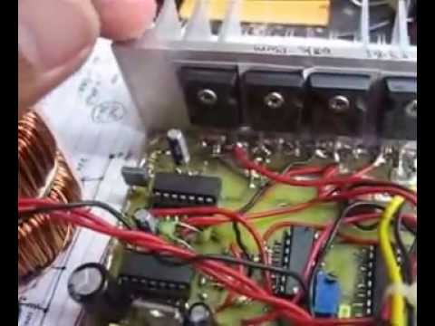
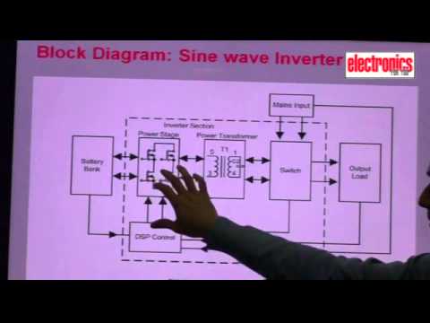
A power inverter device which produces a multiple step sinusoidal ac waveform is referred to as a sine wave inverter. These modified inverters produce a square wave and these are not used to power delicate electronic equipments. The picture was taken in short circuited. That is to say the sg3524 has been wire to produce a fixed pulse width which does not produce a sine wave behavior at the transformer.
To more clearly distinguish the inverters with outputs of much less distortion than the modified sine wave three step inverter designs the manufacturers often use the phrase pure sine wave inverter. Few days ago gohz made a 24v 2000w power inverter in home sharing some design schematics and circuit diagrams. Here is a simple but powerful stable and efficient schematic diagram for a 500w modified sine wave inverter circuit. All the sgca 3524 circuits presented on the net are missing a vital componentcircuit.